Abstract
This paper introduces a fuzzy logic-controlled power system stabilizer to improve the transient stability of Tana Beles Hydro power plant during faulty conditions. The power system stabilizer is integrated into the generator excitation system to enhance the damping effect during low frequency oscillations. To achieve better transient stability, the acceleration and rotor speed deviation of the synchronous machine are used as inputs to the fuzzy logic controller. These variables influence the control of the damping in the generator's mechanical shaft. The designs of system controllers are directly connected to the excitation systems of the plant under wide operating conditions. The system performance has been performed in different scenarios with conventional power system stabilizer (CPSS), PID controller, and fuzzy logic-based power system stabilizer (FLPSS). FLPSS improves settling time of rotor speed, load angle, active power and electrical torque of the plant by 42.9%, 16.7%, 29.2% and 35.7% respectively, over CPSS. Similarly, the system controller improves the settling of rotor speed, load angle, active power and electrical torque of the plant by 33.3%, 9.5%, 29.2% and 25% respectively, over PID controller. The comparison was made between Conventional power system stabilizer (CPSS) and PID controller with Fuzzy logic-based power system stabilizer. The control techniques are simulated over the power transmission single line diagram of Tana Beles Hydropower plant under different scenarios using MATLAB/Simulink software.
Keywords
CPSS, PID, FLPSS, MATLAB /Simulink and Transient Stability
1. Introduction
Electrical power systems are essentially dynamic systems. In such systems, disturbances will happen continuously, which leads to changes in the generator angles and voltages. Once these disturbances are eliminated, the system reaches steady-state operating conditions
| [1] | K. R. D. E. S. A. A. Asma Abbas, "Power System Transient Stability Case Study: Apower sub station inSudan," An international Scientific Journal, pp. 1-18, 16 June 2021. |
[1]
. In today's modern era, all synchronous machines operate in synchronism and supply power to the load. When the load on the generator changes, the rotor speed of synchronous generators either ups or slows down, which in turn affects the frequency, typically within a range of 0.7Hz to 2Hz. However, a Power System Stabilizer (PSS) connected to the generator is essential in restoring the frequency to its normal level. It also enhances the transmission capacity and overall stability of the power system
| [2] | K. Abumuslim, "Stability enhancement of power system with the implementation of power system stabilizer PSS and excitation system IEEE Type-1," Journal of Physics:, pp. 4-9, 2021. |
[2]
.
Power System Stabilizers are critical devices for reducing low-frequency oscillations that occur due to various disturbances, such as faults and load changes. The stability of the electrical power system can be significantly improved by properly designing and tuning the PSS, which helps in damping these oscillations. The PSS is integrated into the generator excitation system to provide an additional signal to the excitation system. It enhances the stability limit by adjusting the generator excitation, thereby delivering positive damping torque to the power swing mode
| [3] | M. S. A. a. e. a. Md. Rashidul Islam a, "Power system stability enhancement through optimal PSS design," e-Prime - Advances in Electrical Engineering, Electronics and Energy, vol. 9, pp. 7-12, 2024. |
[3]
.
The complexity of power system stability analysis and control is further increased by power shortage incidents and intricate cascading failures. The area of this paper is Tana Beles hydropower plant, hich is a run-of- the- river hydroelectric power plant in Ethiopia near Lake Tana. The power plant receives water from the lake through the Tana-Beles inter basin transfer and after utilizing it to produce electricity. The plant has an installed capacity of 460 MW, and it is the second largest power plant in Ethiopia. In this study area, alternators were subjected to electromechanical oscillations due to internal and external causes, which causes for reduction of system component lifetime, loss of synchronism, and, in the worst-case scenario, the risk of partial system collapse. AVR is used by the Tana Beles hydroelectric project to maintain the terminal voltage output of the generators, but it only works to a certain extent. As a result, such a stabilizer has the drawback of being unable to function under various disturbances. Fuzzy logic is an effective technology used today for maintaining stability of electrical systems. Primarily, it depends on the degree of truth. Truth sets enable objects to receive membership grades ranging from 0 to 1 (true or false). These sets are primarily expressed in terms of the linguistic variables that are typically employed to represent a particular fuzzy set in a stability problem
| [4] | S. Fatima, "FUZZY LOGIC (A Comprehensive Description, Key concepts, Architecture and Applications)," International Journal of Uncertainty Fuzziness and Knowledge-Based Systems, vol. 1, no. 1, pp. 1-7, April 2024. |
[4]
.
A fuzzy logic controller has seen widespread use in the power sector recently. There have been numerous reports about the fuzzy control theory-based PSS design. Due to its effectiveness and simplicity, a fuzzy logic-based PSS is preferred for improving transient stability
| [5] | M. S.-A. Z. Mehdi Shafiee, "Enhancing the transient stability of interconnected power systems by designing an adaptive fuzzy-based fractional order PID controller," Energy Reports, vol. 11, pp. 2-6, 2024. |
[5]
. Therefore, this paper uses a fuzzy logic-based power system stabilizer (FLPSS) which is superior to the other power system stabilizers in terms of robustness. FLPSS have great significant to enhance the transient stability of hydropower plants in Ethiopia. which is crucial for maintaining grid reliability during sudden disturbances. The contributions of these efforts have a substantial improvement to mitigate oscillations and greater robustness, ensuring a more stable and efficient power supply.
2. Related Works
Power system researchers and planners have recently paid a lot of attention to transient stability enhancement strategies, which are one of the main causes of unstable power systems.
The author in
| [6] | M. O. Omoigui Funso K. Ariyo, "Investigation of the Damping of Electromechanical Oscillations Using Power System Stabilizers (PSS) in Nigerian 330 kV Electrical Network," Electrical and Electronic Engineering, vol. 2, no. 4, pp. 236-244, 2023. |
[6]
designed an algorithm for investigating the stability of synchronous generators by providing information on damping rotor oscillations. A single-generator-infinite-bus system with and without PSS was examined using MATLAB/Simulink software. The authors were limited for damping electromechanical oscillations of synchronous generators using conventional PSS. The result was fixed for linear problems. However, this paper uses Fuzzy based PSS for damping oscillations caused by nonlinear problems.
The Author in
| [7] | G. Y. Sharie, "Performance analysis and Enhancements of Transient Stability for Sysnchronous Generators using Fuzzy logic Controlled Power System Stabilizer," Bahirdar University official Address, pp. 1-109, 2021. |
[7]
presents this manuscript as Thesis at Bahirdar university to receive a master’s degree, and it was focused on the performance analysis and enhancement of transient stability of synchronous generators for Tana Beles hydropower plant using fuzzy logic controller-based power system stabilizer. The thesis has been modeled for the analysis of excitation systems without controllers, with PID, CPSS, and FLPSS controllers using MATLAB/Simulink software. The simulation result showed the generator parameter response of rotor speed, load angle, active power, electrical torque and terminal voltages of the system. This manuscript is directly related to that thesis, and it was done by me.
Publishers in
| [8] | D. L. a. L. I. Selwa Fetissi, "The Transient Stability Study of a Synchronous Generator Based on the Rotor Angle Stability," International Journal of Electrical and Computer Engineering (IJECE), vol. 5, no. 6, pp. 1319-1327,, December 2021. |
[8]
Studies the transient stability of a single generating unit. The goal of the study is to find out how the critical clearing time of the circuit breakers affects the generator's rotor angle stability in the event of a three-phase breakdown. They used the step-by-step method for various values of fault clearing time to get and determine numerically the kind of rotor angle of the machine. The result determines a major evaluation in critical clearing time to study transient stability. The researchers did not use any types of stabilizers to improve their stability. They evaluate only the time that the fault was cleared. However, this paper uses a controller which improves the stability of the proposed case study.
The authors in
| [9] | S. L. L. V K TayalJagdeep, "Power System Stability Enhancement Using Fuzzy Logic Based Power System Stabilizer," in Conference: Proceedings of the Third International Conference on Soft Computing for Problem Solving, Advances in Intelligent Systems and Computing, 2024. |
[9]
develop a fuzzy logic-controlled power system stabilizer (FLPSS) to enhance the performance of a SMIB system under steady-state and dynamic conditions of the system. Two input FLPSS were taken into consideration to enhance the system's performance, and they reduce the oscillations of the system in the presence of small disturbances. This paper uses fuzzy logic controller to damp electromechanical oscillations of SMIB system under small disturbance. Here, this paper uses fuzzy logic controller for damping electromechanical oscillations of Tana Beles hydropower plant under large disturbance.
Authors in
| [10] | G. p. G. B. G. p. A. M. A. M. Mahdi Saadatmand Gevork B, "Damping of Low-Frequency Oscillations in Power Systems by Large-Scale PV Farms: A Comprehensive Review of Control Methods," pp. 1-24, May 20, 2021. |
[10]
install power system stabilizers to the excitation systems of the generating units to enhance the damping during low-frequency oscillations. The simulations were tested under specific operating conditions and the responses of the stabilizing signal were computed. These are not valid for wide operating conditions due to a sluggish response to sudden disturbances. To overcome these problems, this paper uses a fuzzy logic-controlled power system stabilizer.
Generally, the researchers have found some pros and cons, as stated in the above literature. However, this paper contributes to the Tana Beles hydropower plant by updating the controlling mechanisms of synchronous generators using robustness control mechanisms.
Power system researchers and planners have recently paid a lot of attention to transient stability enhancement strategies, which are one of the main causes of unstable power systems.
3. Transient Stability Enhancement Methods
To enhance the transient stability of the proposed hydropower plant, this paper uses Conventional Power system Stabilizer and PID Controller for comparison purposes with Fuzzy Logic controlled Power system Stabilizer.
3.1. Conventional Power System Stabilizer Method (CPSS)
The conventional stabilizer provides sufficient damping to electromechanical oscillations, but the output voltage is limited to typical maximum and minimum values to restrict the level of generator terminal voltage fluctuation during transient conditions. To reduce low frequency oscillations, the conventional Power System Stabilizer (CPSS) is utilized to generate supplemental control signals to excitation systems.
The speed deviation is used as the signal of stabilizing gain, and it determines the amount of damping introduced by PSS. The washout circuit is provided to eliminate steady-state bias in the output of PSS which is modifying the generator terminal voltage, and it provides the suitable phase lag between the exciter input and generator electrical torque through the help of lead-Lag compensator.
Figure 1. General Structure of CPSS.
3.2. PID Controller Method
To attain the necessary performance level, controllers might have a variety of topologies and design techniques. However, the Proportional-Integral-Derivative (PID) type controller is the most used. A proportional–integral–derivative (PID) controller is a type of control loop feedback mechanism that calculates and outputs a corrective output to rectify the error between a measured process variable and the intended input
| [11] | G. G. P. C. S. Vandana DubeyHarsh, "Role of PID Control Techniques in Process Control System: A Review," Data Engineering for Smart Systems, vol. 4, pp. 3-11, January 2022. |
[11]
.
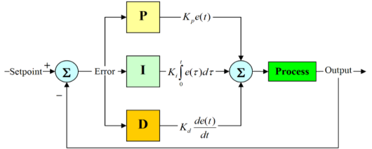
Figure 2. PID controller of the system.
The output of the PID controller, u (t), may be written in terms of the input, e (t), as shown by its name:
(1)
The proportional gain is Kp, the integral gain is Ki, and the derivative gain is Kd.
Three independent parameters are used in the calculation (algorithm): proportional, integral, and derivative values
| [12] | Z. H. Al-Tameemi and A. Hussam, "Transient Stability Improvement of the Power Systems," Electrical Engineering and Computer Science, vol. 12, no. 3, pp. 916-923, December 2024. |
[12]
.
3.3. Fuzzy Logic Controlled Power System Stabilizer (FLPSS) Method
Conventional power system stabilizers have low robust ability compared with the robust controller when the system encounters multiple challenges in wide operating conditions. Since, the paper added fuzzy Logic controller to this stabilizer on the excitation systems of alternators to improve the synchronous generators' transient stability.
In order to avoid using a complicated mathematical model and maintain acceptable performance in a variety of operating conditions, a fuzzy logic-controlled power system stabilizer makes use of linguist information. Fuzzy logic-controlled power system stabilizer being used for enhancement of transient stability and improving the dynamic response of the power system under faulty conditions. The acceleration and rotor speed deviation of the synchronous generator are used as inputs to the fuzzy logic controller in order to increase the power system's stability. These variables have an impact on the dampening of the generator's mechanical shaft. To improve the damping during electromechanical oscillations, a fuzzy logic controller-based power system stabilizer is added to the generator excitation system.
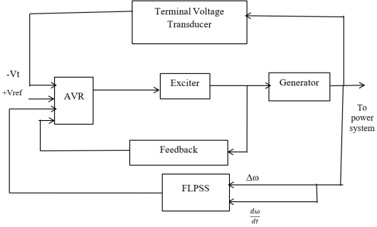
A generator excitation system incorporates components such as automated voltage regulators (AVRs), exciters, and filters with feedback, which aid in system stabilization and maintain a nearly constant terminal voltage
| [13] | P. Dilip and A. ved, "Performance Analysis of Transient Stability and Its Improvement Using Fuzzy Logic Based Power System Stabilizer," vol. 3, no. 2, 2021. |
[13]
.
The fuzzy logic controller receives inputs from the synchronous generators' acceleration and rotor speed variation. Automated voltage regulators (AVRs), exciters, and filters with feedback are included in the generator excitation system. These components help stabilize the system and maintain a virtually constant terminal voltage.
Figure 3. Block diagram of the system with FLPSS.
4. Design of Overall Systems and Controllers
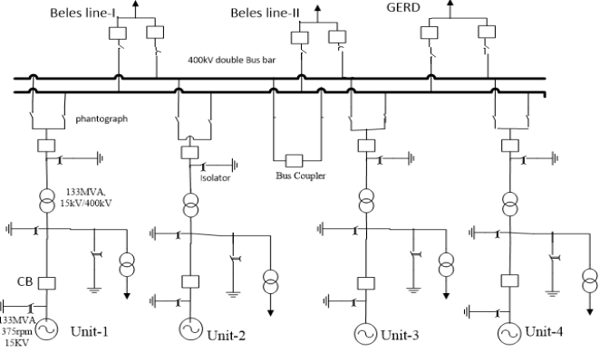
The design of Tana Beles hydropower plant involves multiple components, and a single line diagram typically represents how these components are interconnected in electrical systems. All components in single line diagram play a key role in generation, transmission, and distribution of electrical powers. The study area is interconnected to Bahirdar substation through double transmission lines (Beles line I and line II), and it is also interconnected to Great Ethiopia Renaissance Dam (GERD) with the help of 400kV bus bar.
Figure 4. Single Line diagram of Tana Beles hydropower plant.
This single line diagram is the basis for designing the overall SIMULINK diagram of the plant using MATLAB software as follows.
Figure 5. Simulink diagram of the overall System.
Figure 5 indicates the general design of Tana Beles hydro power plant with fault conditions to test the transient stability status of the plant. The plant's generator data includes a three-phase generator with a rated output of 133MVA, a generator terminal voltage of 11kV, a rated speed of 375 rpm, and it is connected to a 400 kV network via Delta-YN on the low voltage (11kV) side of the transformer and star with neutral on high voltage (400kV) side. The system starts in steady state with the generator supplying 115MW of active power and reactive power of 87.8MVAr. When a three-phase fault is applied to one section of the transmission line, the generator output power and terminal voltage are reduced, causing the system to become transiently unstable.
Now the designs of system controllers for reducing such transient instability of the plant will be as follows.
4.1. Designs of Conventional Power System Stabilizer (CPSS)
The PSS model uses speed deviation as input and Vstab as output signal, which is an input to excitation system of the system.
Figure 6. Designs of CPSS.
This figure represents a CPSS, which consists of a gain block, a washout circuit, and a phase compensator. The gain block, Kstab is simply the PSS gain, which typically ranges from 0.01 to 50. PSS gain is critical because it is responsible for supplying enough damping torque
| [14] | D. Prasenjit, B. Aniruddha and D. and Priyanath, "Tuning of power system stabilizerfor small signal stabilityimprovement of interconnected power system," Tuning of power system stabilizer, no. 3, pp. 1-26, September 2024. |
[14]
. The washout circuit functions as a high-pass filter on the PSS output, passing all essential frequencies while eliminating steady-state signals and modifying generator terminal voltage. The phase compensation block compensates for the lag between PSS output and electrical torque while also eliminating the excitation to electrical torque delay.
4.2. Designs of PID Controller
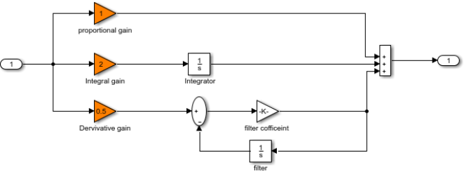
PID controllers are used to improve dynamic responses while also lowering or eliminating steady-state errors. The derivative controller increases the transient response by adding a finite zero to the open-loop plant transfer function. The system uses a parallel algorithm, to design a PID controller. The proportional, integral, and derivative terms are summed to calculate the output of the PID controller, and its values are initially assigned in
Figure 7 below.
Figure 7. Designs of PID controller.
After fine tuning response of the PID controller, Kp, Ki, and Kd values are assigned as shown in
Figure 7 above. This PID controller is directly connected to the excitation systems in each unit of the plant.
4.3. Design of Fuzzy Logic Controlled Power System Stabilizer
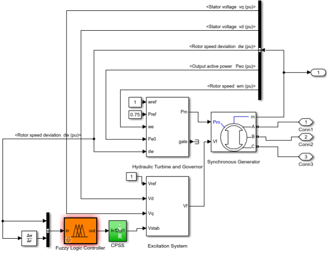
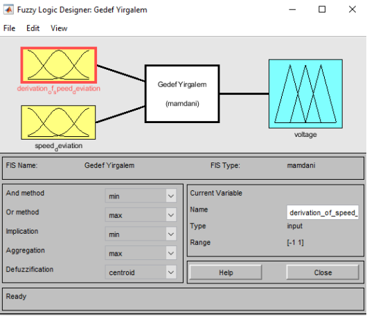
Fuzzy logic-controlled power system stabilizers use the post-disturbance value of the speed deviation and its derivative as inputs, and the heuristic fuzzy control rules are based on the understanding of physical aspects of the power system oscillations. The fuzzy logic-based PSS uses a Mamdani type inference system whose membership functions and consequences are also tuned online by use of perspective rules. The normalized values of speed deviation, as well as its derivatives, are used as inputs to the fuzzy logic controller. Normalization is used to keep the input universe of discourse between -1 and 1, allowing the controller to operate successfully with a wide variety of input variables
| [15] | M. Sujith and A. K. Chandel, "Transient Stability Enhancement of the Power System with Wind Generation," vol. 9, no. 2, pp. 267-278, August 2023. |
[15]
.
Figure 8. Simulink diagram of fuzzy logic-controlled PSS.
4.3.1. Input/Output Variables
Input and output mapped variables are firstly assigned in fuzzy logic controller (FLC). The first input variable to the FLC is the generator speed deviation and the second is acceleration. The output variable to the FLC is the voltage. The fuzzy-logic controller first assigns input and output mapped variables. The generator speed deviation and acceleration are the FLC's first and second input variables, respectively. Voltage serves as the FLC's output variable. The linguistic variables must be chosen after the appropriate variables for the fuzzy controller's input and output have been selected. These variables convert the numerical input values to fuzzy quantities used by the fuzzy controller. The number of linguistic variables describing the fuzzy subsets of a variable varies according to the application. To describe each of the input and output variables, eleven linguistic variables are used. The membership function converts the discrete values into fuzzier variables
| [9] | S. L. L. V K TayalJagdeep, "Power System Stability Enhancement Using Fuzzy Logic Based Power System Stabilizer," in Conference: Proceedings of the Third International Conference on Soft Computing for Problem Solving, Advances in Intelligent Systems and Computing, 2024. |
[9]
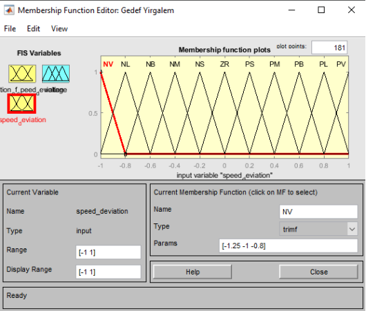
. The degree of membership is defined using triangle membership functions. Here for each input variable, eleven labels are defined namely, NV, NL, NB, NM, NS, ZR, PS, PM, PB, Pl, and PV. Each subset is associated with a Mamdani membership function to form a set of eleven membership functions for each fuzzy variable.
Table 1. Membership functions for fuzzy variables.
Symbol | Meaning |
NV | Negative very large |
NL | Negative large |
NB | Negative big |
NM | Negative medium |
NS | Negative small |
ZR | Zero |
PS | Positive small |
PM | Positive medium |
PB | Positive big |
PL | Positive large |
PV | Positive very large |
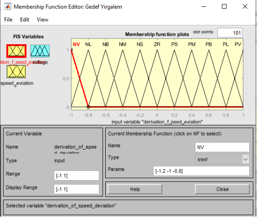
4.3.2. Membership Function Editor
It is a program that allows a programmer to see and modify all membership functions associated with all input and output variables for the entire fuzzy inference system. When the user opens this editor, it works on a fuzzy-inference system that does not yet exist in the workspace.
Figure 10. Membership function for speed deviation.
Figure 11. Membership function for derivation of speed deviation.
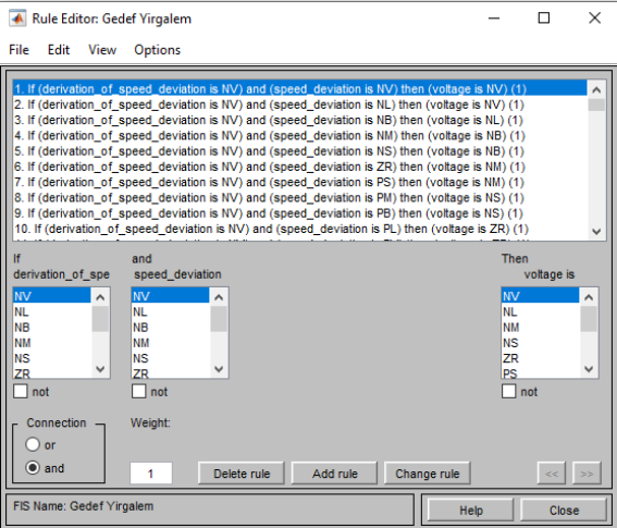
4.3.3. Rule Editor
Rule editor is call up, by choose edit menu rules edit selected.
The Rule Editor allows for the creation of rule statements automatically depending on the input and output variables described in the FIS Editors. From GUI as shown in
Figure 12:
1) Rules are created by selecting an item in each input and output variable box and one connection item and clicking add Rule. Then complete range for the variation of each of the two controller inputs is represented by 11×11 decision table, i.e. 121 rules.
2) Rules are deleted by selecting the rule and clicking Delete Rule.
3) Rules are edited by changing the selection in the variable box and clicking Change Rule.
4) To specify the weight of a rule by typing in a desired number between -1 and 1 in Weight, but do not specify the weight, which is assumed to be unity (1). Each entity shown in
Table 2 represents a rule. The antecedent of each rule conjuncts speed deviation (∆
ω) and acceleration (∆
) fuzzy set values.
Table 2. Decision Table.
∆ω | ∆ |
NV | NL | NB | NM | NS | ZR | PS | PM | PB | PL | PV |
NV | NV | NV | NL | NB | NB | NM | NM | NS | NS | ZR | ZR |
NL | NV | NL | NL | NB | NB | NM | NM | NS | NS | ZR | ZR |
NB | NL | NL | NB | NB | NM | NM | NS | NS | ZR | ZR | PS |
NM | NL | NB | NB | NM | NM | NS | NS | ZR | ZR | PS | PS |
NS | NB | NB | NM | NM | NS | NS | ZR | ZR | PS | PS | PM |
ZR | NB | NM | NM | NS | NS | ZR | ZR | PS | PS | PM | PM |
PS | NM | NM | NS | NS | ZR | ZR | PS | PS | PM | PM | PB |
PM | NM | NS | NS | ZR | ZR | PS | PS | PM | PM | PB | PB |
PB | NS | NS | ZR | ZR | PS | PS | PM | PM | PB | PB | PL |
PL | NS | ZR | ZR | PS | PS | PM | PM | PB | PB | PL | PL |
PV | ZR | ZR | PS | PS | PM | PM | PB | PB | PL | PL | PV |
The values of variables lie between -1 and +1.
The rules guiding the relationship between input and output variables in terms of membership functions are defined as IF-THEN rules statements in the knowledgebase. In this stage, the input variables speed deviation and acceleration are processed by the inference engine that executes 11 ×11 rules represented in rule
Table 2. Each entity shown in
Table 2 represents a rule. The antecedent of each rule conjuncts speed deviation (∆ω) and acceleration (∆ẇ) fuzzy set values. The knowledge required to generate the fuzzy rules can be derived from an offline simulation. Some knowledge can be based on the understanding of the behavior of the dynamic system under control. If the system dynamics are not known or are highly nonlinear, trial and error procedures and experience play an important role in defining the rules. An example of the rule is: If the derivation of speed deviation and speed deviations are NV then output is NV which means the derivation of speed deviation is negative very large and speed deviation is negative very large then the output of fuzzy controller should be negative very large. The procedure for calculating the crisp output of the Fuzzy Logic Controller (FLC) for some values of input variables is based on the following three steps.
Step 1: Determination of degree of firing (DOF) of the rules
The DOF of the rule consequent is a scalar value which equals the minimum of two antecedent membership degrees.
Step 2: Inference Mechanism
The inference mechanism consists of two processes called fuzzy implication and aggregation. The degree of the firing of a rule interacts with its consequent to providing the output of the rule, which is a fuzzy subset. The formulation used to determine how the DOF and the consequent fuzzy set interact to form the rule output is called a fuzzy implication. In fuzzy logic control the most commonly used method for inferring the rule output is a triangular method.
Step 3: Defuzzification
To obtain a crisp output value from the fuzzy set obtained in the previous step mechanism is called defuzzification.
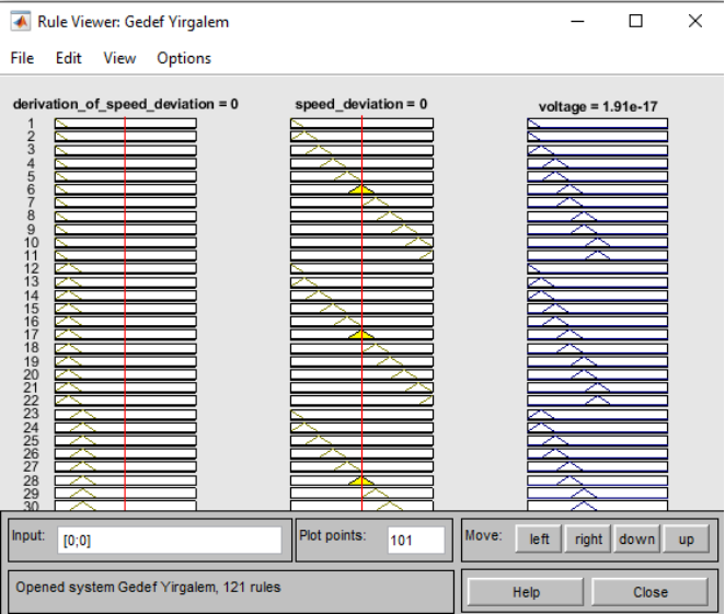
4.3.4. Rule Viewer
It displays a roadmap of the whole fuzzy inference process. It is based on the fuzzy inference. The three plots across the top of
Figure 10 represent the antecedent and consequent of the first rule. Each rule is a row of plots, and each column is a variable. The rule numbers are displayed on the left of each row.
5. Simulation Results and Discussions
Designs of Fuzzy logic-based power system stabilizer to improve transient stability have been measured by the response of the generator parameters associated with time under faulty conditions. This paper demonstrates the simulation of the transient response of synchronous generators in Tana Beles hydropower plant. These machines have identical characteristics in terms of power generating capacity, in terms of their inertia constant, in terms of their output terminal voltage, and in terms of their response to external disturbances. Therefore, with proper modeling of these synchronous machines in MATLAB/SIMULINK, the responses of generator parameters have been studied in excitation systems with Conventional power system stabilizer, PID controller and with fuzzy logic controller-based power system stabilizer.
This study presents the simulation results of the synchronous machines' rotor speed, load angle, electrical power, and electromechanical torques of the plant.
5.1. Results of the System with Conventional Power System Stabilizer
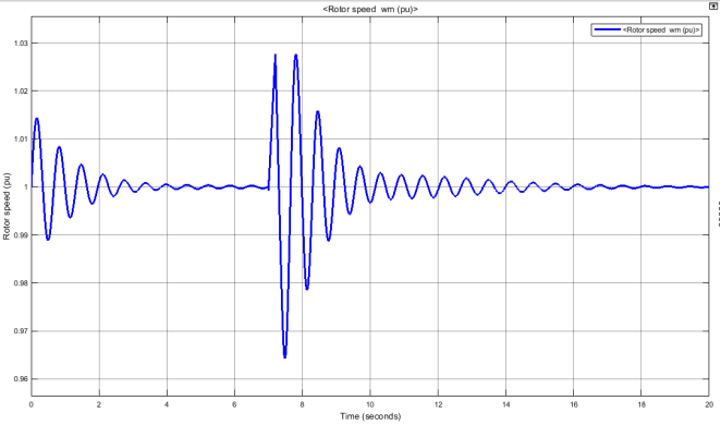
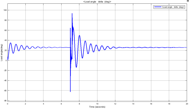
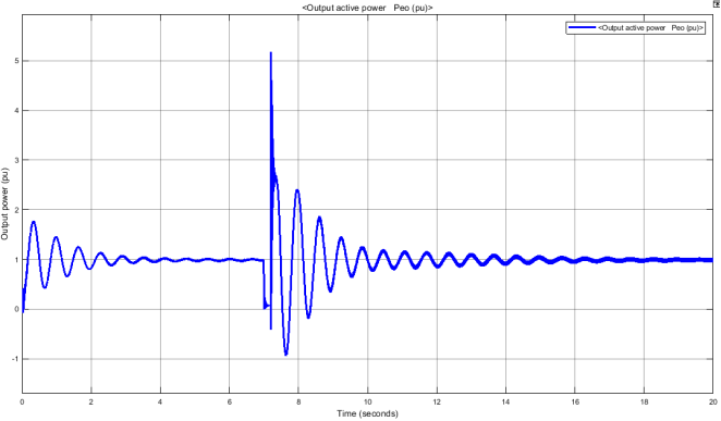
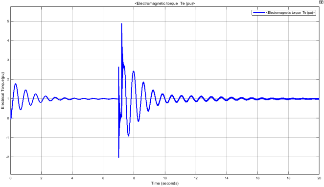
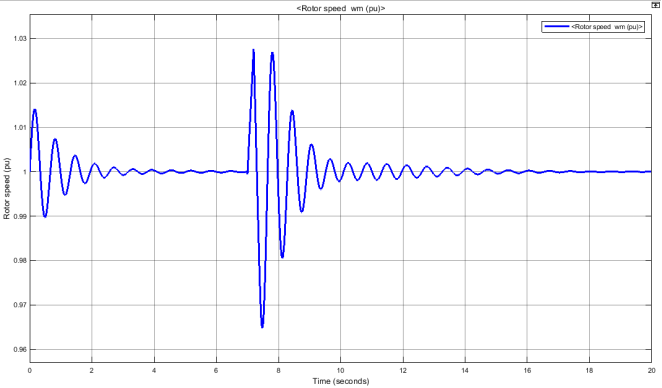
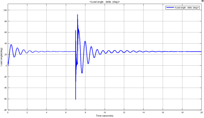
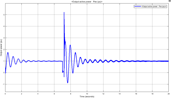
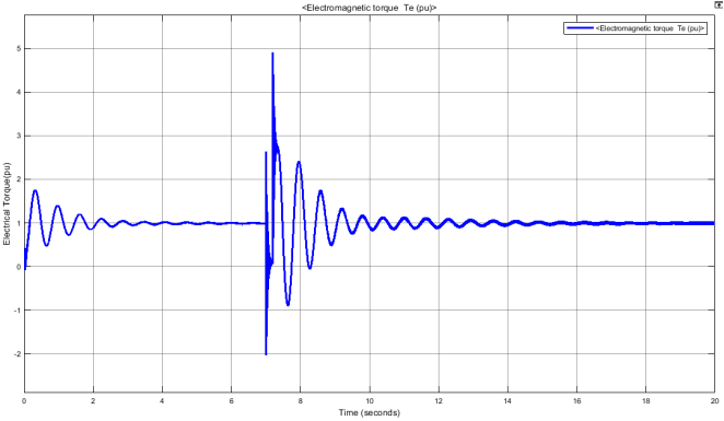
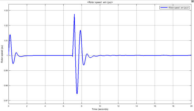
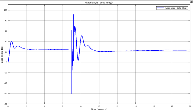
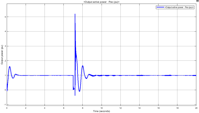
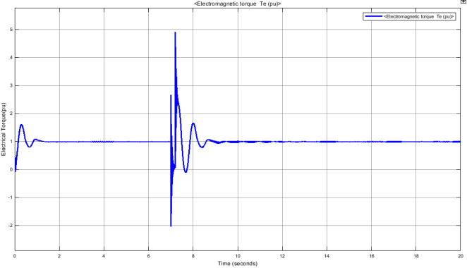
The rotor speed, load angle, output power and electrical torques of the plant becomes transiently unstable through some period and it becomes stable after taking some seconds. The simulation result will be;
Figure 14. Simulation results of rotor speed with CPSS.
Figure 15. Simulation results of load angle with CPSS.
Figure 16. Simulation results of output power with CPSS.
Figure 17. Simulation results of electrical torque with CPSS.
5.2. Results of the System with PID Controller
Similarly, the system parameters result of the plant using PID controller is shown as follows.
Figure 18. Simulation results of rotor speed with PID controller.
Figure 19. Simulation results of load angle with PID controller.
Figure 20. Simulation result of active power with PID controller.
Figure 21. Simulation result of electromechanical torque with PID controller.
5.3. Results of the System Using Fuzzy Logic Based Power System Stabilizer (FLPSS)
The system's simulation results with a fuzzy logic-based power system stabilizer as follows.
Figure 22. Simulation result of rotor speed with fuzzy logic-controlled PSS.
Figure 23. Simulation result of load angle with fuzzy logic-controlled PSS.
Figure 24. Simulation result of output active power with fuzzy logic-controlled PSS.
Figure 25. Simulation result of electrical torque with fuzzy logic-controlled PSS.
When FLPSS is applied in the excitation systems of the plant, the parameters that are simulated in the above are immediately settled within a second. The parameters obtained show that FLPSS achieves better transient enhancement than the conventional power system stabilizer and PID controller.
5.4. Comparisons of Results
Based on the settling times, the performance of the three controllers can be compared as follows:
Table 3. Comparisons of the result.
Parameters | CPSS | PID | FLPSS |
Rotor speed | 14sec | 12sec | 8sec |
Load angle | 12sec | 11sec | 10sec |
Active power | 12sec | 12sec | 8.5sec |
Electrical torque | 14sec | 12sec | 9sec |
FLPSS (Fuzzy Logic Power System Stabilizer) provides the shortest settling times for rotor speed, load angle, active power, and electrical torque, indicating faster damping of oscillations and improved system stability. The PID controller offers moderate improvement over CPSS, while CPSS shows the slowest response. Therefore, FLPSS is the most effective controller for enhancing transient stability and reducing oscillation settling time in the power system.
6. Conclusion
This paper designs a fuzzy logic-controlled power system stabilizer to improve the transient stability for Tana Beles hydropower plant. The output power and terminal voltage of synchronous generators are reduced when a three phases short circuit fault occurs in one section of transmission line (Beles to Bahirdar Line-I). However, when FLPSS is placed in the excitation system of synchronous generators the system becomes stable within a short period of time, even short circuit fault exhibits in the system. The transient stability of rotor speed, load angle, active power, and electrical torque of synchronous generators are improved by reducing settling time of the system. In comparison to CPSS and PID controller, the fuzzy logic controller-based power system stabilizer often greatly enhances damping oscillations and decreases settling time. Finally, the results found in this paper enable us to reduce the settling time of the system, which increases the life span of generation units and minimizes the cost of transmission lines.
Abbreviations
CPSS | Conventional Power System Stabilizer |
FIS | Fuzzy Interface System |
FLC | Fuzzy Logic Controller |
FLPSS | Fuzzy Logic-Controlled Power System Stabilizer |
Ki | Integral Constant |
Kp | Proportional Constant |
Ks | Shaft Stiffness Constant |
PID | Proportional Integral Derivative |
PSS | Power System Stabilizer |
Author Contributions
Gedef Yirgalem Sharie: Conceptualization, Data curation, Methodology, Writing – original draft, Validation
Mebratu Sinte Geremew: Funding acquisition, Investigation, Project administration
Minale Birlie Bizuneh: Resources, Software, Supervision
Hunachew Moges Mitiku: Visualization, Writing – review & editing
Conflicts of Interest
The authors declare no conflicts of interest.
Appendix
Appendix I: Collected Data from the Plant
Table 4.
Transmission line parameters | [7] | G. Y. Sharie, "Performance analysis and Enhancements of Transient Stability for Sysnchronous Generators using Fuzzy logic Controlled Power System Stabilizer," Bahirdar University official Address, pp. 1-109, 2021. |
From bus | To bus | Length (km) | MVA |
Tana beles | Bahirdar -II | 65.79 | 1341 |
Tana beles | GERD | 210 | 133 |
Table 5.
Generator and Transformer parameters | [7] | G. Y. Sharie, "Performance analysis and Enhancements of Transient Stability for Sysnchronous Generators using Fuzzy logic Controlled Power System Stabilizer," Bahirdar University official Address, pp. 1-109, 2021. |
Generator and Transformer Parameters | Ratings |
Generator rating (MVA) | 133 |
Generator voltage rating (KV) | 15 |
Inertia, H(s) | 3.14 |
Frequency, (Hz) | 50 |
Power factor, pf | 0.9 |
Pmax generated, (MW) | 460 |
Speed in rpm | 375 |
Transformer voltage rating, in KV | 15/400 |
Transformer rating (MVA) | 133 |
Length of penstock, (m) | 286 |
Velocity of water, (m/s) | 21.5 |
Rated head, (m) | 315 |
Table 6.
Excitation and Governor parameters | [7] | G. Y. Sharie, "Performance analysis and Enhancements of Transient Stability for Sysnchronous Generators using Fuzzy logic Controlled Power System Stabilizer," Bahirdar University official Address, pp. 1-109, 2021. |
Excitation and Governor Parameters | Ratings |
Low pass filter time constant, Tr(s) | 0.01 |
Regulators gain and time constant [Ka() Ta(s)] | [60, 0.02] |
Damping filter gain and time constant [Kf() Tf(s)] | [0.03, 1] |
Regulator output limits and gain [Efmin, Efmax, kp] | [-5, 5, 0] |
Servo- motor [Ka(), Ta(sec)] | [1.2, 0.5] |
Gate opening limits [gmin, gmax(pu), vgmin, vgmax(pu/s)] | [0, 1, -0.1, 0.1] |
Permanent drop and regulator [Rp(), Kp(), Ki(), Kd(), Td(s)] | [0.04, 0.8, 0, 0.6, 0.01] |
Hydraulic turbine time constant, Tw(sec) | 2 |
Table 7.
Power system stabilizer parameters | [7] | G. Y. Sharie, "Performance analysis and Enhancements of Transient Stability for Sysnchronous Generators using Fuzzy logic Controlled Power System Stabilizer," Bahirdar University official Address, pp. 1-109, 2021. |
PSS parameters | Values |
Stabilizer gain, kstab() | 10 |
Washout time for stabilizer, Tw(sec) | 10 |
Lead lag time constants [Tn1, Tn2 (sec)] | [0.2492, 0.16835] |
Proportional gain for PID, kp() | 1 |
Integral gain, KI () | 2 |
Derivative gain () | 0.5 |
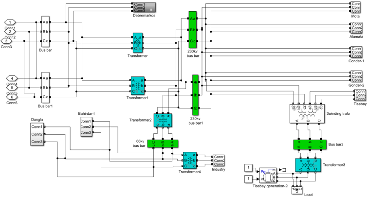
Appendix II: Simulink Diagram of Bahirdar Substation-II
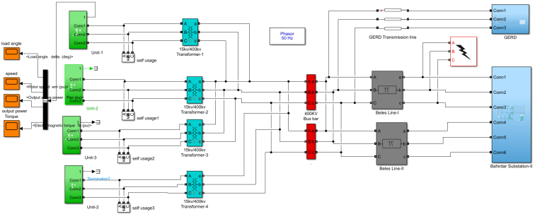
Figure 26. MATLAB/Simulink diagram of Bahirdar Substation_II.
References
| [1] |
K. R. D. E. S. A. A. Asma Abbas, "Power System Transient Stability Case Study: Apower sub station inSudan," An international Scientific Journal, pp. 1-18, 16 June 2021.
|
| [2] |
K. Abumuslim, "Stability enhancement of power system with the implementation of power system stabilizer PSS and excitation system IEEE Type-1," Journal of Physics:, pp. 4-9, 2021.
|
| [3] |
M. S. A. a. e. a. Md. Rashidul Islam a, "Power system stability enhancement through optimal PSS design," e-Prime - Advances in Electrical Engineering, Electronics and Energy, vol. 9, pp. 7-12, 2024.
|
| [4] |
S. Fatima, "FUZZY LOGIC (A Comprehensive Description, Key concepts, Architecture and Applications)," International Journal of Uncertainty Fuzziness and Knowledge-Based Systems, vol. 1, no. 1, pp. 1-7, April 2024.
|
| [5] |
M. S.-A. Z. Mehdi Shafiee, "Enhancing the transient stability of interconnected power systems by designing an adaptive fuzzy-based fractional order PID controller," Energy Reports, vol. 11, pp. 2-6, 2024.
|
| [6] |
M. O. Omoigui Funso K. Ariyo, "Investigation of the Damping of Electromechanical Oscillations Using Power System Stabilizers (PSS) in Nigerian 330 kV Electrical Network," Electrical and Electronic Engineering, vol. 2, no. 4, pp. 236-244, 2023.
|
| [7] |
G. Y. Sharie, "Performance analysis and Enhancements of Transient Stability for Sysnchronous Generators using Fuzzy logic Controlled Power System Stabilizer," Bahirdar University official Address, pp. 1-109, 2021.
|
| [8] |
D. L. a. L. I. Selwa Fetissi, "The Transient Stability Study of a Synchronous Generator Based on the Rotor Angle Stability," International Journal of Electrical and Computer Engineering (IJECE), vol. 5, no. 6, pp. 1319-1327,, December 2021.
|
| [9] |
S. L. L. V K TayalJagdeep, "Power System Stability Enhancement Using Fuzzy Logic Based Power System Stabilizer," in Conference: Proceedings of the Third International Conference on Soft Computing for Problem Solving, Advances in Intelligent Systems and Computing, 2024.
|
| [10] |
G. p. G. B. G. p. A. M. A. M. Mahdi Saadatmand Gevork B, "Damping of Low-Frequency Oscillations in Power Systems by Large-Scale PV Farms: A Comprehensive Review of Control Methods," pp. 1-24, May 20, 2021.
|
| [11] |
G. G. P. C. S. Vandana DubeyHarsh, "Role of PID Control Techniques in Process Control System: A Review," Data Engineering for Smart Systems, vol. 4, pp. 3-11, January 2022.
|
| [12] |
Z. H. Al-Tameemi and A. Hussam, "Transient Stability Improvement of the Power Systems," Electrical Engineering and Computer Science, vol. 12, no. 3, pp. 916-923, December 2024.
|
| [13] |
P. Dilip and A. ved, "Performance Analysis of Transient Stability and Its Improvement Using Fuzzy Logic Based Power System Stabilizer," vol. 3, no. 2, 2021.
|
| [14] |
D. Prasenjit, B. Aniruddha and D. and Priyanath, "Tuning of power system stabilizerfor small signal stabilityimprovement of interconnected power system," Tuning of power system stabilizer, no. 3, pp. 1-26, September 2024.
|
| [15] |
M. Sujith and A. K. Chandel, "Transient Stability Enhancement of the Power System with Wind Generation," vol. 9, no. 2, pp. 267-278, August 2023.
|
Cite This Article
-
APA Style
Sharie, G. Y., Geremew, M. S., Bizuneh, M. B., Mitiku, H. M. (2026). Design of a Fuzzy Logic-Based Power System Stabilizer to Improve Transient Stability of Tana Beles Hydropower Plant. International Journal of Electrical Components and Energy Conversion, 11(1), 7-28. https://doi.org/10.11648/j.ijecec.20261101.12
 Copy
|
Copy
|
 Download
ACS Style
Sharie, G. Y.; Geremew, M. S.; Bizuneh, M. B.; Mitiku, H. M. Design of a Fuzzy Logic-Based Power System Stabilizer to Improve Transient Stability of Tana Beles Hydropower Plant. Int. J. Electr. Compon. Energy Convers. 2026, 11(1), 7-28. doi: 10.11648/j.ijecec.20261101.12
Copy
|
Download
AMA Style
Sharie GY, Geremew MS, Bizuneh MB, Mitiku HM. Design of a Fuzzy Logic-Based Power System Stabilizer to Improve Transient Stability of Tana Beles Hydropower Plant. Int J Electr Compon Energy Convers. 2026;11(1):7-28. doi: 10.11648/j.ijecec.20261101.12
Copy
|
Download
-
@article{10.11648/j.ijecec.20261101.12,
  author = {Gedef Yirgalem Sharie and Mebratu Sinte Geremew and Minale Birlie Bizuneh and Hunachew Moges Mitiku},
  title = {Design of a Fuzzy Logic-Based Power System Stabilizer to Improve Transient Stability of Tana Beles Hydropower Plant},
  journal = {International Journal of Electrical Components and Energy Conversion},
  volume = {11},
  number = {1},
  pages = {7-28},
  doi = {10.11648/j.ijecec.20261101.12},
  url = {https://doi.org/10.11648/j.ijecec.20261101.12},
  eprint = {https://article.sciencepublishinggroup.com/pdf/10.11648.j.ijecec.20261101.12},
  abstract = {This paper introduces a fuzzy logic-controlled power system stabilizer to improve the transient stability of Tana Beles Hydro power plant during faulty conditions. The power system stabilizer is integrated into the generator excitation system to enhance the damping effect during low frequency oscillations. To achieve better transient stability, the acceleration and rotor speed deviation of the synchronous machine are used as inputs to the fuzzy logic controller. These variables influence the control of the damping in the generator's mechanical shaft. The designs of system controllers are directly connected to the excitation systems of the plant under wide operating conditions. The system performance has been performed in different scenarios with conventional power system stabilizer (CPSS), PID controller, and fuzzy logic-based power system stabilizer (FLPSS). FLPSS improves settling time of rotor speed, load angle, active power and electrical torque of the plant by 42.9%, 16.7%, 29.2% and 35.7% respectively, over CPSS. Similarly, the system controller improves the settling of rotor speed, load angle, active power and electrical torque of the plant by 33.3%, 9.5%, 29.2% and 25% respectively, over PID controller. The comparison was made between Conventional power system stabilizer (CPSS) and PID controller with Fuzzy logic-based power system stabilizer. The control techniques are simulated over the power transmission single line diagram of Tana Beles Hydropower plant under different scenarios using MATLAB/Simulink software.},
 year = {2026}
}
Copy
|
Download
-
TY  - JOUR
T1  - Design of a Fuzzy Logic-Based Power System Stabilizer to Improve Transient Stability of Tana Beles Hydropower Plant
AU  - Gedef Yirgalem Sharie
AU  - Mebratu Sinte Geremew
AU  - Minale Birlie Bizuneh
AU  - Hunachew Moges Mitiku
Y1  - 2026/08/17
PY  - 2026
N1  - https://doi.org/10.11648/j.ijecec.20261101.12
DO  - 10.11648/j.ijecec.20261101.12
T2  - International Journal of Electrical Components and Energy Conversion
JF  - International Journal of Electrical Components and Energy Conversion
JO  - International Journal of Electrical Components and Energy Conversion
SP  - 7
EP  - 28
PB  - Science Publishing Group
SN  - 2469-8059
UR  - https://doi.org/10.11648/j.ijecec.20261101.12
AB  - This paper introduces a fuzzy logic-controlled power system stabilizer to improve the transient stability of Tana Beles Hydro power plant during faulty conditions. The power system stabilizer is integrated into the generator excitation system to enhance the damping effect during low frequency oscillations. To achieve better transient stability, the acceleration and rotor speed deviation of the synchronous machine are used as inputs to the fuzzy logic controller. These variables influence the control of the damping in the generator's mechanical shaft. The designs of system controllers are directly connected to the excitation systems of the plant under wide operating conditions. The system performance has been performed in different scenarios with conventional power system stabilizer (CPSS), PID controller, and fuzzy logic-based power system stabilizer (FLPSS). FLPSS improves settling time of rotor speed, load angle, active power and electrical torque of the plant by 42.9%, 16.7%, 29.2% and 35.7% respectively, over CPSS. Similarly, the system controller improves the settling of rotor speed, load angle, active power and electrical torque of the plant by 33.3%, 9.5%, 29.2% and 25% respectively, over PID controller. The comparison was made between Conventional power system stabilizer (CPSS) and PID controller with Fuzzy logic-based power system stabilizer. The control techniques are simulated over the power transmission single line diagram of Tana Beles Hydropower plant under different scenarios using MATLAB/Simulink software.
VL  - 11
IS  - 1
ER  -
Copy
|
Download







 Share This Article
 Twitter
 Linked In
 Facebook